Hero Section (Bullet Summary at Top):
- Solenoid valves use electromagnetism to open or close fluid flow — essential in automation and process control.
- Key components: coil, plunger, spring, orifice — all working together to control the valve state.
- This guide explains the basic working principle with diagrams, types of solenoid valves, and where they’re used.
- Covers 2-way, 3-way, normally closed, and normally open valve types — plus tips from field installs.
- Includes wiring basics, troubleshooting tips, and selection checklist.
How Does a Solenoid Valve Work in Simple Terms?
If you’re just starting out with solenoid valves, here’s how I explain it to new techs on the floor:
A solenoid valve is basically a switch for fluids — it uses electricity and magnetism to open or close the flow of a liquid or gas.
Here’s what happens:
- When you apply voltage (like 24VDC or 110VAC) to the coil, it becomes an electromagnet.
- That magnetic field pulls up a metal plunger inside the valve body.
- When the plunger moves, it opens or closes an orifice — this controls whether fluid flows or not.
- The valve can start or stop flow in just a few milliseconds — perfect for fast automation tasks like air cylinders, dosing, or water spray control.
- It works with air, water, oil, steam, and many industrial fluids — depending on the material and seal.
This simple concept is what makes solenoid valves so widely used — from coffee machines to cleanrooms to massive factory lines.
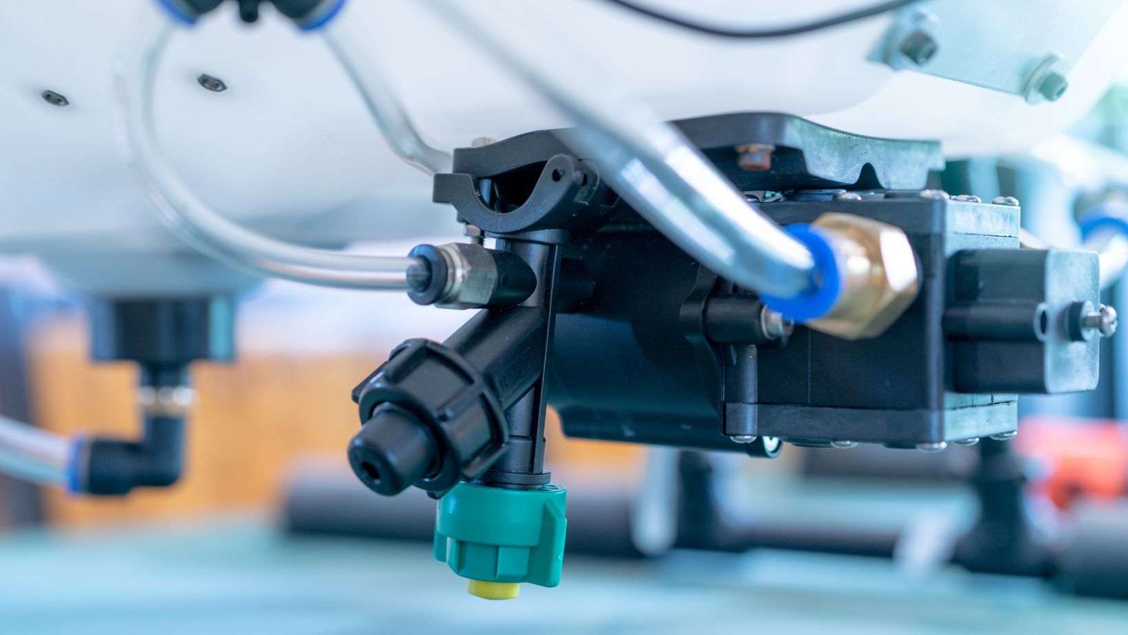
Add a labeled diagram here showing:
- Coil
- Plunger
- Spring
- Valve body
- Flow direction arrows (open vs. closed)
🔍 Tip from the field: If the valve isn’t clicking when energized, check the coil with a multimeter first. A burnt coil is one of the most common failure points.
What Are the Main Parts Inside a Solenoid Valve?
This table effectively summarizes the core internal components of a solenoid valve and their functions — perfect for beginners and technicians who want a quick reference. Here’s why it works:
| Part | Function |
| Coil (Solenoid) | Creates magnetic field |
| Plunger / Armature | Moves to open/close valve |
| Spring | Pushes plunger back when de-energized |
| Valve body | Controls the fluid direction |
| Orifice | Flow control opening |
H2: What Are the Types of Solenoid Valves?
When selecting a solenoid valve for a system, you’ll often see them categorized in two major ways: by function (number of ports/flow paths) and by default state (how the valve behaves when de-energized). Here’s how I explain it to junior techs when we’re wiring up a new skid or retrofitting a pneumatic line.
H3: By Function
- 2-Way Solenoid Valve
This is the simplest type. It has one inlet and one outlet — basically acting like an on/off switch for flow.
I’ve used 2-way valves for turning water or compressed air on/off in tank fill systems and conveyor pneumatic lines. - 3-Way Solenoid Valve
This valve has one inlet and two outlets, or vice versa. It can divert flow between two paths.
Ideal for basic actuation of single-acting cylinders or pilot valves. I used a lot of these in irrigation controllers for zone switching. - 5-Way Solenoid Valve
Typically used in double-acting pneumatic actuators, like what you see in packaging machinery or robotic arms.
It handles extend/retract control for cylinders — especially when both air inlets need control.
By State
- Normally Closed (NC)
This is the most common type. The default state blocks flow when the solenoid is not energized. Once you power it, the coil opens the valve.
I recommend NC valves for fail-safe designs — if power goes out, the valve automatically closes. - Normally Open (NO)
This type stays open by default, and closes when energized.
I used NO valves for a thermal bleed line — we needed flow by default, but occasionally shut it using a PLC signal.

Pro Tip: Always check the datasheet for valve orientation (horizontal or vertical) and actuation pressure. Solenoid valves often need a minimum differential pressure to operate properly — that’s a common install mistake I’ve had to troubleshoot.
What Is the Working Principle of a Solenoid Valve? (Step-by-Step)
This table breaks down the solenoid valve working principle into a simple 4-step process — something I often explain to new technicians during hands-on training.
| Step | Action |
| 1. Coil energizes | Electric current flows |
| 2. Magnetic field builds | Pulls plunger against spring |
| 3. Orifice opens/closes | Changes flow state |
| 4. Coil de-energizes | Spring returns plunger to rest |
H2: What Media and Systems Use Solenoid Valves?
Solenoid valves are widely used across industries because they offer fast, reliable control of fluid or gas flow. Based on my field installations, here’s where you’ll typically find them:
- Water Purification Units
Used for controlling flow in filtration, reverse osmosis (RO), and UV treatment loops. - Compressed Air Systems (Pneumatics)
Essential in actuating air cylinders or directing flow paths in automation setups. - HVAC Control Systems
Used in chilled water loops, zone valve control, or dampers for airflow direction. - Oil & Gas Pipelines
Deployed for pilot gas control, emergency shut-off systems, or process gas switching. - Irrigation Systems
Common in agricultural and commercial setups — solenoids control zone water flow. - Household Appliances
Found in washing machines, dishwashers, and even espresso machines — for automated water dosing.
Field Tip:
When working in dusty or humid environments (like irrigation or food plants), I always recommend using valves with IP65-rated enclosures or better. Premature failure due to coil moisture ingress is more common than you’d think.
What Are the Advantages of Solenoid Valves?
In my hands-on work across food plants, pneumatic systems, and water treatment facilities, solenoid valves consistently prove their value. Here’s why engineers and techs like me rely on them:
- Fast and Precise Switching
Solenoid valves respond in milliseconds — perfect for high-speed automation and timed processes. Whether it’s dosing, diverting, or shutting off flow instantly, they deliver. - Remote Control Capability
You can operate solenoid valves via PLCs, timers, or relay signals, making them ideal for distributed control systems without manual intervention. - Compact and Easy to Integrate
Their small footprint allows for installation in tight panels, modular machines, or inline piping. Most models come with standardized fittings and brackets. - Low Power Consumption
Especially in 12V/24V DC models, energy draw is minimal — a plus in mobile systems or battery-backed applications. - Safe Fail-Mode Options
Choose between normally closed (fail-safe shutoff) or normally open (fail-safe open) depending on your system’s safety requirement. This is critical for applications like steam control or gas handling.
Pro Tip:
When I design a loop where safety matters — like steam injection or fuel cut-off — I always spec a normally closed solenoid with manual override and LED status indicator. It’s cheap insurance against a process gone wrong.
H2: What Are the Common Issues With Solenoid Valves?
| Problem | Cause | Fix |
| Valve not opening | Coil burnt or blocked plunger | Check coil resistance |
| Leaking valve | Damaged seal or debris | Clean or replace seal |
| Buzzing sound | AC noise or low voltage | Check power quality |
How to Select the Right Solenoid Valve for Your Application
When I’m specifying solenoid valves for a new system — whether it’s a pneumatic conveyor or a water dosing skid — I always follow a checklist to make sure the valve matches the real-world operating conditions. Here’s a step-by-step approach that works in the field:
Step 1: Define Your Media (Water, Air, Gas, Oil)
Start by identifying what fluid the valve will control. Media properties like viscosity, temperature, and cleanliness can dictate the valve type and material. For example, oil needs a stronger coil and tighter seals compared to clean water.
Step 2: Choose Normally Closed (NC) or Normally Open (NO)
Decide how the valve should behave without power:
- NC (Normally Closed): Valve blocks flow until energized — safer for most systems.
- NO (Normally Open): Valve allows flow until power is applied — used in some emergency relief or cooling circuits.
Choose based on fail-safe conditions for your process.
Step 3: Select Coil Voltage
Check your control panel voltage and choose a matching solenoid:
- 12V or 24V DC: Common in mobile or PLC-driven systems
- 24V AC or 220V AC: Typical for industrial mains supply
Always confirm compatibility to avoid coil burnout or erratic actuation.
Step 4: Check Pressure and Flow Ratings
Make sure the valve is rated for your system’s:
- Operating pressure (in bar or psi)
- Flow rate (often measured in Cv or L/min)
Undersizing leads to restriction; oversizing can reduce control precision.
Step 5: Choose Valve Material
Match body and seal materials to your media:
- Brass: Great for water and non-corrosive fluids
- Stainless steel (SS): Required for corrosive chemicals or food-grade lines
- Plastic (e.g., PVDF or nylon): Lightweight, cost-effective for low-pressure or aggressive media
⏱️ Step 6: Check Response Time & Cycle Life
Fast-acting valves (under 50 ms) are ideal for automation tasks like pneumatic cylinders or filling lines. High-cycle valves last longer in systems with rapid on/off duty — look for specs like “cycle life > 10 million”.
Step 7: Review Connector & Wiring Requirements
Some solenoids come with DIN connectors, flying leads, or terminal blocks. Choose what’s easiest to install in your panel or field box. Also, check if the valve needs external protection like IP65 or better for washdown areas.


